
Objectives
• Use software that shows how data travels through the Internet.
• Use the ping utility to test connectivity to a remote network.
• Construct a visual map of connectivity from your network to a remote network.
Background / Preparation
In order to perform this lab, Internet connectivity is required. On a PC, open a web browser to ensure
connectivity exists before beginning this lab.
This lab has an optional first step of downloading and installing a free program that can be used to determine
the path a packet takes through the Internet. This program may be free, but it also may be copyrighted. Also,
it may be that you are not permitted on a campus computer to download and install software. Check with the
instructor or student assistant if you are unsure.
The following resources will be required:
• Windows-based computer with Internet connectivity
• Ability to download and install freeware software (optional)
• Access to the Run command
Step 1: (Optional) Download and install a free program
a. Open a search engine such as Google (www.google.com), Yahoo (www.yahoo.com), or Search (http://search.com).
b. Which words do you think would give you the best result if you are searching for a visual program that allows you to trace how data (a packet) travels through the Internet? Write your search words
Answer:
Keyword yang saya gunakan adalah : download software gratis
c. Type the words you chose in the Search field. Locate and download the software and install it. Normally, the website has a link to the download site or you can click the words “Download” or “Download Now”. When you download any freeware, remember the location on the hard drive, flash drive, or disk media where you saved the program. Write down where the download is saved.
Answer:
saya memilih salah satu situs yang saya dapat di dalam search engginer, kemudian mendownload salah satu programnya, kemudian menyimpannya di hard drive.
d. What is the name of the program you installed?
Answer:
nama program yang saya download dan nantinya akan saya install adalah: Video Converters
Step 2: Locate web sites
a. Using the search engine again, locate five businesses with a web server, which are located in a country different from your own.
b. Write the names of the five business web sites.
Answer:
1) Sophie Martin
2) Pocari sweat
3) Cocacola
4) microsoft
5) unilever
c. Using the search engine again, locate a business in your own country that has a web site that is accessible.
Answer:
Step 3: (Optional) Use downloaded visual trace route tool
a. Using the software you have downloaded and installed, use the tool to determine the path which the packet takes to reach one of the remote country destinations. Each tool normally allows you to type a URL. The program should either list or visually display the path taken by the packet.
b. How many hops does the packet take to get from your computer to the destination computer?
Answer:
jumlah hops yang ditemukan untuk sampai ke tujuan adalah 14 hops
c. If your tool also provides time information, write down how long it took for the packet to reach the first hop?
Answer:
Untuk mencapai hops pertama dibutuhkan 14 ms
d. Use the tool to determine the path to another foreign country site.
e. How many hops does the packet take to get from your computer to the destination computer?
Answer:
f. Use the tool to determine the path to a web site in your own country.
g. Was the time it took to reach a web site in your own country shorter or longer?
Answer:
h. Try to think of an instance where the time it takes to reach a web server in your own country would be longer than it takes to reach another country’s web server?
Answer:
Step 4: Use the tracert command
a. Click the Start button, click the Run option, type cmd, and press Enter. An alternate way to get to the command prompt is to click Start > All Programs > Accessories > Command Prompt.
b. From the command prompt, type tracert and press Enter. Options that can be used with the tracert command are shown. Items shown in square brackets [ ] are optional. For example, the first option
that can be used with the tracert command is –d. If someone was to type tracert –d www.cisco.com,
then the command issued to the computer is to trace the route to www.cisco.com, but do not try to
resolve IP addresses to names. The target_name parameter is mandatory (it does not have brackets
around it) and it is replaced with the destination network. In the previous example of tracert –d
www.cisco.com, www.cisco.com is the target_name.
c. Which tracert option would be used to designate that only 5 hops could be used to search for the device address on the destination network?
Jawab:

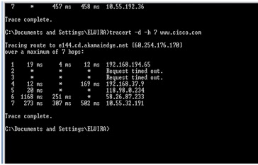
d. Write the full command that would be typed to trace a route to www.cisco.com and instruct the computer to not search for it after seven hops.
Answer:

e. Using one of the remote country destination addresses (use the same address as the one you used with the visual tool if possible) use the tracert command to determine how many hops it takes to reach the remote web server. Write the number of hops and the destination.
Answer:
f. The tracert command uses Internet Control Message Protocol (ICMP) echo request messages to determine the path to the final destination. The path displayed is a list of IP addresses assigned to routers that connect to one another to form the path. The ICMP packets contain a value called a
Time To Live (TTL). The TTL value is 30 by default on a Microsoft-based PC and each router through which the packet passes, decrements that value by 1 before sending the packet on to the next router in the path. When the TTL value reaches 0, the router that has the packet sends an ICMP time exceeded message back to the source.
The tracert command determines the path by sending the first ICMP echo request message with a TTL of 1 and then increases that TTL value by 1 until the target responds or the maximum number of hops is reached. The path is determined by examining the ICMP time exceed messages that are sent
back by routers along the way and by the ICMP echo reply message that is returned from the destination. Routers that do not return the ICMP time exceed messages are shown by a row of asterisks (*).
How many hops does your tracert command show that the packet went through?
Answer:
Hops pada coment tracert yang menunjukkan paket dikirim ada 1 yaitu pada alamat 10.1.1.5 karena pada command prompt hanya hops tersebut yang tidak mememiliki tanda (*).
Step 5: Use the pathping command
a. A similar command that can be used on a Windows XP computer is pathping. This command combines the abilities of the tracert command with the ping command. From the command prompt, use the pathping command to determine the IP addresses of the routers used to create the packet path to another foreign country address. An example of the pathping command used to trace the path to Cisco is pathping www.cisco.com.
b. How many hops did the pathping command display to your remote destination?
Answer:

c. When do you think that you would ever use a tool like pathping or tracert?
Answer:
Fungsi traceroute adalah program sederhana untuk melihat hop-hop dari computer kita ke suatu IP address di Internet
Pathping adalah perintah teks berbasiskan Windows yang dapat digunakan untuk menyediakan informasi mengenai jalur (path) data yang digunakan atau ditempuh ketujuan, latency (delay) jaringan dan informasi hilangnya paket pada setiap hop di jalur perangkat intermediate antara komputer asal (pengirim) hingga ke komputer tujuan (penerima).
Step 6: (Optional) Use the whois function
a. Some of the freeware tools include an option to perform a whois function. Whois is a separate program or integrated with a tool similar to tracert or pathping. It displays (and sometimes has a link) who owns the web link of either the destination URL (such as cisco.com) or any of the links along the path. Explore the freeware tool that you have downloaded and installed and determine if it has a whois function. If it does, use it to determine who owns the domain name of one of the previous destinations used.
b. Why would you want to use the whois function?
Answer:
Step 7: Reflection
With a classmate, compare all of the commands used in this lab. Describe the purpose and benefit of each one. Which do you think is the most useful command?
Jawab:
Ø tracert
mengirim IP yang berbeda untuk menargetkan pada saat kelangsungan hidup (TTL) nilai dari "Internet Control Message Protocol (ICMP)" echo paket, Tracert prosedur diagnostik untuk menentukan rute dibawa ke target. Persyaratan untuk setiap router di jalur paket sebelum paket forwarding pada setidaknya penurunan TTL 1. TTL pada paket tersebut dikurangi ke 0, router harus "ICMP telah habis waktunya" pesan kembali ke sistem sumber.
Tracert mengirimkan TTL sebagai respon paket, dan mengirim dalam proses berikut ini untuk setiap TTL bertambah dengan 1, sampai respon sasaran atau TTL mencapai maksimum, untuk menentukan rute. Dengan memeriksa router antara mengirim kembali "ICMP telah habis waktunya" pesan untuk menentukan routing. Beberapa router tidak bertanya langsung dibuang oleh TTL berakhir paket, yang tidak melihat pada utilitas Tracert.
perintah Tracert untuk mencetak perintah untuk kembali "ICMP telah habis waktunya" pesan di jalan proksimal dari interface router untuk daftar. Jika Anda menggunakan opsi-d, utilitas Tracert tidak memeriksa semua alamat IP pada DNS.
Ø Pathping
perintah pathping adalah melacak rute alat, akan ping dan tracert fungsi perintah dan dua alat tidak memberikan informasi lain bersama-sama. pathping perintah untuk beberapa waktu untuk mengirim paket untuk mencapai tujuan akhir dari jalan setapak di setiap router, dan kemudian hasilnya komputer berdasarkan data paket kembali dari masing-masing hop. Seperti perintah menampilkan paket pada suatu router atau link yang diberikan pada besarnya kerugian, sehingga Anda dapat dengan mudah mengidentifikasi masalah jaringan dapat menyebabkan router atau link. Beberapa pilihan yang tersedia, tabel berikut.
Ø Dari dua penjelasan di atas dan pengalaman pada setiap percobaan maka kami memilih command pathping yang lebih useful
Untuk lab selanjutnya tidak bisa kami lakukan percobaanya karena keterbatasan alat, dan jarang sekali ada lab yang kosong. Insyaallah akan kami lengkapi jika alat yang di butuhkan telah tersedia.
Lab 4.5.3 Building Straight-Through and Crossover UTP Cables
Objective
• Build and test straight-through and crossover Unshielded Twisted Pair (UTP) Ethernet network cables.
Background / Preparation
In this lab you will build and terminate Ethernet straight-through patch cables and crossover cables. With a straight-through cable, the color of wire used by pin 1 on one end is the same color used by pin 1 on the other cable end, and similarly for the remaining seven pins. The cable will be constructed using either TIA/EIA T568A or T568B standards for Ethernet, which determine which color wire is used on each pin. Straight-through patch cables are normally used to connect a host directly to a hub or switch or to a wall plate in and office area.
With a crossover cable the second and third pairs on the RJ-45 connector at one end of the cable are reversed at the other end. The pinouts for the cable are the T568A standard on one end and the T568B standard on the other end. Crossover cables are normally used to connect hubs and switches or can be used to directly connect two hosts to create a simple network. This is a two-part lab that can be done individually, in pairs, or in groups.
The following resources will be required:
• Two 0.6 to 0.9m (2 to 3 ft.) lengths of cable, Category 5 or 5e
• A minimum of four RJ-45 connectors (more may be needed if mis-wiring occurs)
• An RJ-45 crimping tool
• An Ethernet cable tester
• Wire cutters
Part A: Build and test an Ethernet straight-through patch cable
Step 1: Obtain and prepare the cable
a. Determine the length of cable required. This could be from a device such as a computer to the device to which it connects (like a hub or switch) or between a device and an RJ-45 outlet jack. Add at least 30.48 cm (12 in.) to the distance. The TIA/EIA standard states the maximum length is 5 m (16.4 ft.). Standard Ethernet cable lengths are usually .6 m (2 ft.), 1.83 m (6 ft.), or 3.05 m (10 ft.).
b. Which length of cable did you choose and why did you choose this length?
Answer:
saya akan mememilih
c. Cut a piece of cable to the desired length. Stranded UTP cable is commonly used for patch cables (the cables between an end network device such as a PC and an RJ-45 connector) because it is more durable when bent repeatedly. It is called stranded because each of the wires within the cable is made up of many strands of fine copper wire, rather than a single solid wire. Solid wire is used for cable runs that are between the RJ-45 jack and a punch-down block.
d. Using wire strippers, remove 5.08 cm (2 in.) of the cable jacket from both ends of the cable.
Step 2: Prepare and insert the wires
a. Determine which wiring standard will be used. Circle the standard.
[T568A | T568B]
b. Locate the correct table based on the wiring standard used.
c. Spread the cable pairs and arrange them roughly in the desired order based on the standard chosen.
d. Untwist a short length of the pairs and arrange them in the exact order needed by the standard. It is very important to untwist as little as possible. The twists are important because they provide noise cancellation.
e. Straighten and flatten the wires between your thumb and forefinger.
f. Ensure the cable wires are still in the correct order as the standard.
g. Cut the cable in a straight line to within 1.25 to 1.9 cm (1/2 to 3/4 in.) from the edge of the cable jacket. If it is longer than this, the cable will be susceptible to crosstalk (the interference of bits from one wire with an adjacent wire).
h. The tang (the prong that sticks out from the RJ-45 connector) should be on the underside pointing downward when inserting the wires. Insert the wires firmly into the RJ-45 connector until all wires are pushed as far as possible into the connector.
Step 3: Inspect, crimp, and re-inspect
a. Visually inspect the cable and ensure the right color codes are connected to the correct pin numbers.
b. Visually inspect the end of the connector. The eight wires should be pressed firmly against the end of the RJ-45 connector. Some of the cable jacket should be inside the first portion of the connector. This provides strain relief for the cable. If the cable jacket is not far enough inside the connector, it may eventually cause the cable to fail.
c. If everything is correctly aligned and inserted properly, place the RJ-45 connector and cable into the crimper. The crimper will push two plungers down on the RJ-45 connector.
d. Visually re-inspect the connector. If improperly installed, cut the end off and repeat the process.
Step 4: Terminate the other cable end
a. Use the previously described steps to attach an RJ-45 connector to the other end of the cable.
b. Visually re-inspect the connector. If improperly installed, cut the end off and repeat the process.
c. Which standard [T568A | T568B] is used for patch cables in your school?
Jawab:
Standar RJ45 yang dipakai di jurusan Elektronika ialah T568B
Step 5: Test the cable
a. Using a cable tester, test the straight-through cable for functionality. If it fails, repeat the lab.
b. (Optional) Use the cable to connect a PC to a network.
c. (Optional) Click the Start button and select the Run option.
d. (Optional) Type cmd and press Enter.
e. (Optional) From the command prompt, type ipconfig.
f. (Optional) Write down the default gateway IP address.
Jawab:
Machine dependent
g. (Optional) From the command prompt, type ping followed by the default gateway IP address. If the cable is functional, the ping should be successful (provided that no other network problem exists and the default gateway router is connected and functional).
Part B: Build and test an Ethernet crossover cable
Step 1: Obtain and prepare the cable
a. Determine the length of cable required. This could be from a hub to a hub, hub to switch, switch to switch, computer to router, or from one computer to another computer. Add at least 30.48 cm (12 in.) to the distance. Which length of cable did you choose and why did you choose this length?
Jawab:
Untuk menghemat biaya
b. Cut a piece of cable to the desired length and, using wire strippers, remove 5.08 cm (2 in.) of the cable jacket from both ends of the cable.
Step 2: Prepare and insert the T568A wires
a. Locate the T568A table at the beginning of the lab.
b. Spread the cable pairs and arrange them roughly in the desired order based on the T568A standard.
c. Untwist a short length of the pairs and arrange them in the exact order needed by the standard. It is very important to untwist as little as possible. Twists are important because they provide noise cancellation.
d. Straighten and flatten the wires between your thumb and forefinger.
e. Ensure the cable wires are in the correct order based on the standard.
f. Cut the cable in a straight line to within 1.25 to 1.9 cm (1/2 to 3/4 in.) from the edge of the cable jacket. If it is longer than this, the cable will be susceptible to crosstalk (the interference of bits from one wire with an adjacent wire).
g. The tang (the prong that sticks out from the RJ-45 connector) should be on the underside pointing downward when inserting the wires. Insert the wires firmly into the RJ-45 connector until all wires are pushed as far as possible into the connector.
Step 3: Inspect, crimp, and re-inspect
a. Visually inspect the cable and ensure the right color codes are connected to the correct pin numbers.
b. Visually inspect the end of the connector. The eight wires should be pressed firmly against the RJ-45 connector. Some of the cable jacket should be inside the first portion of the connector. This provides for cable strain relief which can eventually cause the cable to fail.
c. If everything is correctly aligned and inserted properly, place the RJ-45 connector and cable into the crimper. The crimper will push two plungers down on the RJ-45 connector.
d. Visually re-inspect the connector. If improperly installed, cut the end off and repeat the process.
Step 4: Terminate the T568B cable end
a. On the other end, use the previously described steps (but use the T568B table and standard) to attach an RJ-45 connector to the cable.
b. Visually re-inspect the connector. If improperly installed, cut the end off and repeat the process.
c. Which standard [T568A | T568B] would you rather use at home if you have or would like to have a home network?
Step 5: Test the cable
a. Using a cable tester, test the crossover cable for functionality. If it fails, repeat the lab.
b. Use the cable to connect two PCs.
c. On both computers, click the Start button and select Run.
NOTE: If the Run command is unavailable on your PC, visually check the LED status lights on the NIC card. If they are on (usually green or amber) the cable is functional.
d. On both computers, type cmd and press Enter.
e. On both computers from the command prompt, type ipconfig.
f. Write the IP address of both computers.
Computer 1:192.168.0.1
Computer 2: 192.168.0.2
g. From the command prompt of one computer, type ping followed by the IP address of the other computer. If the cable is functional, the ping should be successful. Do the ping on the other computer as well.
NOTE: The Windows Firewall on the target computer must be temporarily disabled for the ping to be successful. Refer to Lab 3.1.5 if you need help with this. If you disable the firewall, be sure to re-enable it.
Step 6: Reflection
a. Which part of making these cables did you find the most difficult? Compare your views with a classmate.
b. Are all four pairs of cables twisted the same amount? Discuss the reasons why or why not.
The twisting of the pairs is done to cancel electromagnet interference. The twisting ratio is different for each cable pair so that they do not fit closely together. If they did fit snugly together it would not help the EMI cancellation feature as much
c. Ask a local business or check a site such as http://www.workopolis.com/ to see how much a beginning cable installer earns and which criteria they look for in a cable installer. Write the information you discover in the space provided.
d. Many technicians keep a crossover cable in their toolkit. When do you think that you would use a crossover cable and when do you think a network technician would use this cable
Lab 4.5.4 Terminating UTP Cables
Objectives
· Use a punch down tool to terminate an RJ-45 wall jack.
· Install an RJ-45 jack in a wall plate.
· Use a punch down tool to terminate a UTP cable at a patch panel.
·
Background / Preparation
In this lab you will wire an RJ-45 data jack for installation in a wall plate using a punch-down tool. This is done frequently when installing cabling in an office environment. The punch tool is also used to terminate the other end of the cable at a patch panel punch-down block. The punch tool uses spring-loaded action to push wires between metal pins, while at the same time skinning the sheath away from the wire. This ensures that the wire makes a good electrical connection with the pins inside the jack. The punch tool also cuts off any extra wire.
A Category 5/5e straight-through patch cable with an RJ-45 connector normally plugs into a data jack or outlet to connect a PC to the network. It is important to use Category 5 or 5e rated jacks and patch panels with Category 5 or 5e cabling in order to support Fast Ethernet (100 Mbps) and Gigabit Ethernet (1000 Mbps). The process of punching down wires into a data jack in an office area is the same as punching them down at a patch panel in a wiring closet. This lab can be performed individually, in pairs, or in groups.
The following resources are required:
· 60-90 cm (2-3 feet) length of cable, either Category 5 or 5e.
· RJ-45 data jack—If RJ-45 data jacks are installed on both ends of the cable, two jacks will be needed
and the installation can be tested by inserting cable with RJ-45 connectors and a simple cable
continuity tester. More jacks may also be needed if errors are made.
· Category 5/5e wall plate.
· Patch panel.
· Punch tool, type 110.
· UTP cable stripper.
· Wire cutters.
· Two known good straight-through patch cables for testing (optional).
Step 1: Strip the sheath
a. Remove the cable sheath 2.54 cm (1 inch) from the end of the cable.
Step 2: Position wires in data jack
b. Position wires in the proper channels on the RJ-45 jack maintaining the twists as close to the jack as possible. The diagram that follows shows an example of how to place the wires with one type of jack.
c. Most jacks have the channels color-coded to indicate where the wires go. The following photo of the jack shows one model. Jacks are typically stamped to indicate whether they are T568A or T568B.
Step 3: Punch down the data jack
a. Use the punch tool to push conductors into the channels. Make sure to position the cutting side of the punch tool so that it faces the outside of the jack. If this is not done, it will cut the wire being punched. Try tilting the handle of the punch tool a little to the outside, so it will cut better.
b. If any wire remains attached after using the punch tool, simply twist the ends gently to remove them. Then place the clips on the jack, and tighten them. Make sure that no more than 1.27 cm (one half inch) of untwisted wire is between the end of the cable jacket and the channels on the jack.
Step 4. Attach the faceplate.
a. Snap the jack into the faceplate by pushing it from the back side. Make sure when this is done, that the jack is right-side up so the clip faces down when the wall plate is mounted.
b. Use the screws to attach the faceplate to either the box or to the bracket. If there is a surfacemounted box, keep in mind that it might hold 30-60 cm (1-2 feet) of excess cable. Then it will be necessary to either slide the cable through the tie-wraps, or pull back the raceway that covers it, in order to push the excess cable back into the wall. If there is a flush-mounted jack, all that is needed is to push the excess cable back into the wall.
Step 5: Punch down the patch panel
a. On the opposite end of the cabling, remove the jacket 2.54 cm (1 inch) from the cable.
b. Lay the wires down in the patch panel so that the colors of the wires correspond exactly to the colors indicated on the pin locations in the same manner as the data jack was punched down.
c. Keep the sheath within .64 cm (¼ inch) of where the wires begin branching out to their pin locations.
d. Do not untwist the wires more than necessary to lay them down at the pin locations. A good way to keep from untwisting too much is to hold down the wires next to the patch panel with one finger while using the other hand to pull apart each end as you lay it across the connector.
e. The following figure shows a large punch down patch panel with carefully routed cabling.
Step 6: Test the data jack and patch panel terminations with a basic cable tester (optional)
a. Obtain two straight-through Ethernet patch cables and verify they both function properly using a simple cable tester.
b. Connect one end of one of the straight-through Ethernet patch cables to the data jack outlet and one end of the other straight-through cable to the jack at the patch panel.
c. Insert the opposite ends of the two cables into a simple cable tester and check for continuity from end to end through both patch cables, the data jack, and the patch panel. Did the cable run test good from end to end?
Jawab:
Yes. If not, try to analyze where the problem is and repeat the connections if possible with another wall jack and patch panel port
Step 7: Reflection (optional)
a. Take a tour of a wiring closet that contains patch panels and punch-down blocks. Was there any other type of devices that might use similar techniques to attach wires? What do you think attaches to these cables?
Jawab
but a common connector is a phone punch-down block
b. What do you think are some of the drawbacks and advantages of having a job installing network cabling?
Jawab:
Ya sama
Lab 4.5.5 Testing UTP Cables
Objectives
• Explore the wire mapping features of a cable meter.
• Explore the Cable Test feature—Pass/Fail features of a cable meter.
• Explore the Cable Length feature of a cable meter.
• Use a cable tester to check for the proper installation of unshielded twisted-pair (UTP) Category 5/5e according to TIA/EIA-568 cabling standards in an Ethernet network.
Background / Preparation
Wire maps can be very helpful in troubleshooting cabling problems with UTP cable. A wire map allows the network technician to verify which pins on one end of the cable are connected to which pins on the other end.
Basic cable tests can be very helpful in troubleshooting cabling problems with UTP. The cabling infrastructure or cable plant in a building is expected to last at least ten years. Cable-related problems are one of the most common causes of network failure. The quality of cabling components used, the routing and installation of the cable, and quality of the connector terminations will be the main factors in determining how trouble-free the cabling will be.
Prior to starting the lab, the teacher or lab assistant should have several correctly-wired Category 5 cables to test. The cables should include both straight-through and crossover. There should also be several Category 5 cables created with problems such as poor connections and split pairs to be used in testing. Cables should be numbered to simplify the testing process and to maintain consistency. A cable tester should be available that can test at least continuity, cable length, and wire map. This lab can be performed individually, in pairs, or in groups.
The following resources are required:
• Good Category 5 straight-through cables of different colors
• Good Category 5 crossover cables (T568A on one end and T568B on the other end)
• Category 5 straight-through cables of different colors and different lengths with open connections in the middle, or one or more conductors shorted at one end
• Category 5 straight-through cable with a split pair mis-wire
• A cable meter to test cable length, continuity, and wire map
Step 1: Set up the cable meter
a. On the cable meter, select the WIRE MAP function of the cable tester.
b. Change the setup options of the cable tester until the tester is set to the following cabling settings:
Tester Option | Desired Setting - UTP |
CABLE: | UTP |
WIRING: | 10BASE-T OR EIA/TIA 4PR |
CATEGORY: | CATEGORY 5 |
WIRE SIZE: | AWG 24 |
CAL TO CABLE? | NO |
BEEPING: | ON or OFF |
LCD CONTRAST: | From 1 through 10 (brightest) |
c. Once the meter is set up, exit the setup mode.
Step 2: Test Cabling Procedure
a. For each cable to be tested use the following procedure. Place one end of the cable into the RJ-45 jack labeled UTP/FTP on the tester. Place the other end of the cable into the RJ-45 female coupler, and then insert the cable identifier into the other side of the coupler. The coupler and the cable identifier are accessories that come with many cable meters.
Step 3: Use the Wire Map meter function
a. The Wire Map function and a Cable ID Unit can be used to determine the wiring of both the near and far end of the cable. One set of numbers displayed on the LCD screen is the near end, and the other set is the far end. Perform a Wire Map test on each of the cables provided. Fill in the following table
based on the testing results for each Category 5 cable. For each cable, write down the identifying number of the cable and the cable color. Also write down whether the cable is straight-through or crossover, the tester screen test results, and a description of the problem.
Answers will vary depending upon the type of cable used for testing and type of problem
Step 4: Use the Length meter function
a. Using the tester LENGTH function, perform a basic cable test on the same cables used previously. Fill in the additional information for each cable. Step 5: Test data jack and patch panel terminations for wire map, length and mis-wire (optional)
a. Using the data jack and patch panel cable from the previous lab, connect one end of one of the straight-through Ethernet patch cables to the data jack outlet and one end of the other straight-through cable to the jack at the patch panel.
b. Insert the opposite end of one of the cables into the cable meter and the other into the coupler and cable identifier. Check for wire map, length and mis-wire from end to end through the patch cables, the data jack, and the patch panel. Did the cable run test good from end to end? What were the results? Wire map:
Jawab:
Straight-through
c. Total cable run length:
Jawab:
tergantung
d. Any mis-wires?
Jawab:
tidak
Step 6: Reflection
a. If you were on a job and did not have a cable meter to test, what other methods can be used?
Jawab:
but one answer is that you could connect a different device to the cable to see if the cable activates the NIC on the device. Also, an alternate jack in the same area could be used
Tidak ada komentar:
Posting Komentar